MITSUBISHI
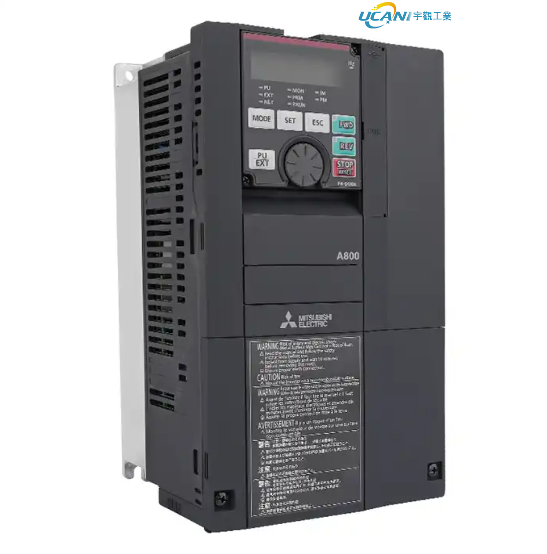
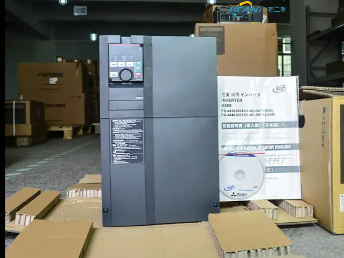
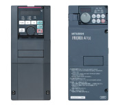
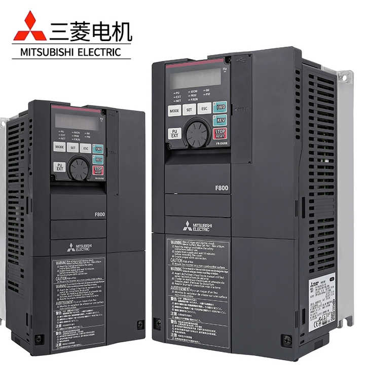
FR-A800 Series
- Product description: FR-A800 Series
● IP55 compatible model
● Separated converter type
-
*1 : Models can be alternatively indicated with the inverter rated current (SLD rating).
(For the FR-A842-P and the FR-A846, the current rating is LD or ND. However, the rated current used to represent the model is the SLD rated current of the standard model.) - *2 : Specification differs by the type as follows.
| Type | Monitor output | Initial setting | |||
|---|---|---|---|---|---|
|
Built-in EMC filter |
Control logic |
Rated frequency |
Pr.19 Base frequency voltage |
||
|
FM (terminal FM equipped model) |
Terminal FM (pulse train output) Terminal AM (analog voltage output (0 to ±10 VDC)) |
OFF | Sink logic |
60 Hz |
9999 (same as the power supply voltage) |
|
CA (terminal CA equipped model) |
Terminal CA (analog current output (0 to 20 mADC)) Terminal AM (analog voltage output (0 to ±10 VDC)) |
ON | Source logic | 50 Hz |
8888 (95% of the power supply voltage) |
- *3 : Available for the 5.5K or higher.
- *4 : For using the 75K or higher inverter and a 75 kW or higher motor, always install a DC reactor (FR-HEL), which is available as an option.
- *5 : Always install the converter unit (FR-CC2(-P)). (Not required when a high power factor converter (FR-HC2) is used.)
-
Variety of functions
● Check the energy saving effect at a glance
- ● You can check the energy saving effect on the energy saving monitor.
- ● The measured output power amount can be output in pulses.
● Reduce power consumption during standby
-
● Control circuits other than those for power-related parts can be operated with 24 VDC power supplied from an external power source.

Since the control circuit can use the external 24 VDC, other power control circuits can stay OFF while no driving is required, and that saves the standby energy. - ● By turning the cooling fan ON/OFF based on the inverter status, wasteful power consumption during stoppages can be reduced.
● Save energy with Optimum excitation control
The excitation current is constantly adjusted to drive the motor in the most efficient method which leads to energy saving.
For example, with optimum excitation control with motor load torque of 10% when using the SF-JR, motor efficiency has increased by approximately 15% over the previous V/F control method.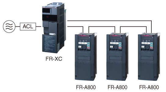
● Effective use of regenerative energy (option)
Multiple inverters can be connected to the power regeneration common converter (FR-XC)/high power factor converter (FR-HC2) via a common PN bus.
Regenerative power is used at other inverters, and surplus energy is returned to the power supply, resulting in energy saving.
The 315K or higher models are inverter-converter separated types, which are suitable for power regeneration.
Safety standards compliance
Controls with safety functions can be easily performed. The Safe Torque Off (STO) safety function is supported by the inverter. The inverter with the safety function can comply with the safety standards without incurring much expenses.
● PLe and SIL3 are supported as standard.
- ● ISO13849-1:2015 Category 3/PLe
- ● IEC62061:2015 / IEC61800-5-2:2016 / IEC61508:2010 SIL3
*1: Safety communication is available between a safety programmable controller and a remote I/O module.
*2: One MC is required to shut off the power at an activation of the protective function.
Reliable and secure maintenance
Standard 24 VDC power supply for the control circuit
In addition to the existing power supply input terminals (R1 and S1) of the control circuit, 24 VDC input is equipped as standard.
The 24 VDC power supplied from outside can be fed to the control circuit locally, enabling the parameter settings, communication operation and safety maintenance without turning ON the main power.
Prevention of trouble with temperature monitoring
The inverter is equipped with an internal temperature sensor, which outputs a signal when the ambient temperature is high.
This facilitates the detection of rises in temperature inside the inverter following cooling fan malfunction, or rises in ambient temperature due to inverter operating conditions.
Long life components and life check function
Long life components
● The service life of the cooling fans is now 10 years*3.
The service life can be further extended by ON/OFF control of the cooling fan.● Capacitors with a design life of 10 years*3*4 are adapted.
With these capacitors, the service of the inverter is further extended.● Estimated service lifespan of the long-life parts
Components Estimated lifespan of the FR-A800 *3 Guideline of JEMA *5 Cooling fan 10 years 2 to 3 years Main circuit smoothing capacitor 10 years*4 5 years Printed board smoothing capacitor 10 years*4 5 years -
*3 : Surrounding air temperature: Annual average of 40°C (free from corrosive gas, flammable gas, oil mist, dust and dirt).
The design life is a calculated value from the LD rating and is not a guaranteed product life. - *4 : Output current: 80% of the inverter LD rating
- *5 : Excerpts from "Periodic check of the transistorized inverter" of JEMA (Japan Electrical Manufacturer’s Association).
Enhanced life diagnosis function
● An internal thermal sensor is equipped to all inverters as standard, which enables monitoring of the installation environment.
Use this function as a guide for the life diagnosis.
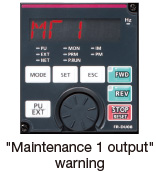
● Maintenance timers are available for up to three peripheral devices, such as motor and bearing.
Quick reaction to troubles
Easy fault diagnosis
● The operating status (output frequency, etc.) immediately before the protection function activates can be stored in the inverter built-in RAM with the trace function. The stored data (trace data) can be copied to a USB memory device or directly imported to a computer, facilitating trouble analysis using the inverter setup software (FR Configurator2).
Trace data stored in the built-in RAM is deleted when the power is turned OFF or the inverter is reset.
● •Clock setting is now available in addition to the already-available cumulative energization time. The time and date at a protective function activation are easily identified. (The clock is reset at power-OFF.) The date and time are also saved with the trace data, making the fault analysis easier.
By using the real-time clock function with the optional liquid crystal display (LCD) operation panel (FR-LU08) (when using battery), the time is not reset even when the power supply is turned OFF.
Renewal assurance
Intercompatibility with existing models
● The inverter installation method is the same as that for the FR-A700 series, eliminating any concerns over replacement.
Furthermore, FR-A700 series control circuit terminal blocks can be installed with the use of an option (FR-A8TAT).● The terminal response adjustment function allows a user to adjust the response speed in accordance with the existing facility.
● The conversion function of Inverter Setup Software (FR Configurator2) enables parameter copy from an FR-A700 and even from an FR-A500 (to be supported soon).
Reasons for high quality
Design considering the hazardous environment
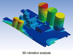
3D-vibration analysis is performed to confirm the vibration resistance. The analysis is also useful to find the best layout position and to further improve the product's rigidity.
Assuming a hazardous service condition, the product reliability is thoroughly assessed in the design stage. Every effort is made to ensure the best quality of the Mitsubishi inverter.*6Heat control for high quality
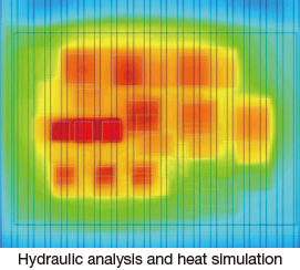
Resistance against heat is what makes an inverter reliable.
A well-designed heat-resistant power module is essential in a reliable inverter. From the power module's design stage, its heat resistance is carefully considered.*6- *6 : The usage beyond the product's specified service condition is not guaranteed.
Related Products
Categories
Latest News
Contact Us
Contact: Gloria
Phone: +8613681981380
Tel: +86 021-64556477
Add: Room 312, Factory Building, No. 338 Shuangbai Road, Minhang District, Shanghai